Wednesday, August 26, 2015

Testing Search Coils

After assembling the circuit and making a search coil (as seen in my last post), I ran a series of tests. Some of the tests let the circuit run uninterrupted, while in others I moved a bag of coins towards and away from the search coil. Overall, the coil was able to detect the coins, but its range was much less than the range DZL claims to have gotten using the same setup.

For the first test, I plugged the stripped enameled copper wire directly into the breadboard, uploaded the Serial_Output sketch, and left the setup to run on my dining room table for an hour and twenty minutes. At that point I was using the original example sketch, which didn't print out a timestamp (just the frequencies). At first all the frequencies were reading zero; when I unplugged and replugged in some wires on the breadboard, it started working.


The frequencies were erratic at first, then rose sharply. After about a minute, they stabilized near 86 kHz (DZL's circuit oscillated at about 160 kHz). However, the frequencies continued to increase very gradually over the rest of the test:

So while the signal didn't break down in the way the commentor described, it wasn't exactly stable either, increasing at a rate of approximately 3.5 Hz per minute (a range of about 12 Hz).

For the next test, I used the same coil and the same setup. I let the circuit run for about an hour then slowly introduced a bag of coins. The coins started 12 in above the coil, and were lowered down to be level with the coil, then raised back up to 12 in. The process took place over a 15 second period. During the uninterrupted portion of the test, the frequencies varied more erratically, not showing the steady gradual increase seen in the first test:


During the coin test, there was a very slight increase in frequency when the coins were within an inch and a half of the coil:

This shows that the circuit is fundamentally working, but it didn't have a very impressive range. Many of the other metal detector tutorials I read recommended using 70 or more turns of wire in the search coil, while DZL only used 30. I also thought that since I had to push in the wires every time to get the circuit to work, it might help to solder hookup wire onto the ends of the enameled copper wire, to get a more reliable electrical connection. I decided to first test adding hookup wire to the ends of the enameled copper.


Hookup wire is a thicker wire, usually 22 AWG, that is commonly used with breadboards. I stripped a little insulation from the ends of the hookup wire (I used nail clippers, since the wire strippers I had were the wrong size for 22 AWG). Then I wrapped the end of the enameled copper wire (with enamel removed) around the the hookup wire 7 or 8 times, and covered the connection with solder. I then repeated the last test, running the circuit for an hour uninterrupted, then lowering the bag of coins towards the coil (from 12 in) over a 15 second period. After the initial increase (from seconds 0 to 50), the frequency was remarkably stable, ranging between 86.873 kHz and 86.892 kHz (a range of 19 Hz) over the next four minutes.

Later on, the frequency looked more erratic...

...but actually only varied from 86.937 kHz to 86.948 kHz over the course of the ten minute period, a range of 11 Hz. This is less variation than we saw in the four minutes after ramp-up. Over the next three ten-minute periods, the frequency varied by 22 Hz, 30 Hz, and 599 Hz. Then the graph suddenly dropped by 585 Hz, after which it was very stable (variation of 9 Hz) until the bag of coins was introduced. I don't know how to account for the 585 Hz drop- all I can think of is that someone must have moved metal towards or away from the circuit at that moment, but to the best of my knowledge the room was undisturbed during the test.

This graph shows the 585 Hz drop and the peak from the coins.


The increase in frequency during the coin test is noticeable during the seconds marked 33 to 41 on the following graph:

  
The bag of coins was lowered the same way as in the previous tests, moving 24 inches over approximately 15 seconds. The frequency change was noticeable over an 8 second period, which suggests the coil can detect the bag of coins when it is within 5 or 6 inches.

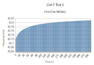
For the next test, I constructed a new 30 cm coil, this time with about 70 turns of wire. The first change I noticed was that the frequency of this coil was lower, around 41 kHz instead of 86 kHz. After the initial ramp-up,

the frequency was quite stable, increasing linearly and very gradually:


If we divide the thirty minutes between the ramp-up (first five minutes) and the last 10 minutes (which include the coin test) into three ten minute periods, the frequency varied by 15 Hz, 28 Hz, and then 5 Hz. This is comparable to the stability of the first coil, but without the erratic jumps and dips in frequency- throughout that half-hour period, the frequency changes linearly, which could make this signal easier to work with than the signal generated by the first coil.

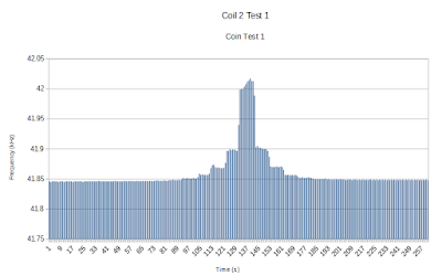
For this test, I had added the timestamp to the Arduino code (this version of the code can be found here), so that I could more accurately time the coin test. I held the bottom of the bag of coins level with each inch mark on the ruler for ten seconds before lowering or raising it:

As the graph shows, there are four recognizable "levels" on each side of the peak, which means that the coil was able to detect the bag when it was within 4 inches of the top of the coil. Since DZL says that his metal detector was able to find a single coin at a depth of almost 6 inches, it's clear that mine is not measuring up.

However, I do think it will improve with better code. In this post, when I say that the coil detected the bag, what I really mean is that I, looking at the graph with the naked eye, detected a change in frequency. For example, if the program can get a more sophisticated idea of the default frequency (for example, by taking a running average of the previous minute(s)), it would be able to distinguish between noise and small changes introduced by the presence of metal. At some point I'll return to the metal detector and work on improving the code, but for the moment I've switched gears and am going to focus on drivetrains for a while.

My First Metal Detector

Over the past month or so, I've made some progress with building the metal detector circuit for my robot. Its detection range is shorter than predicted by the blog I got the circuit from, but I think that can be improved by more sophisticated programming.

First I built the circuit, using the Arduino Duemilanove and a breadboard. A commentor on the original blog post said that he had trouble prototyping on a breadboard because the "parasitic inductance, capacitance, and resistance" caused the signal to break down after a few minutes. I decided to prototype it on a breadboard anyway and then transfer to something else later (maybe perfboard?) if it became an issue. I haven't observed the signal "breaking down", although the frequency does tend to slowly increase over time.

Here's my circuit on the breadboard:

It was easy once I figured out that the capacitors on the diagram were in nanofarads, not microfarads.


It's messy, I know- I wanted to test it before I went to the trouble of trimming everything down, and since there's still a possibility that I'll do the final version on perfboard or something, I haven't cleaned it up yet. If you want to know more about what breadboards are or how they work, I covered it in a post last summer.

After assembling the circuit, I made the search coil. I wanted to try out a few different sizes of coils, to see which size would work best for this project. This site gives a thorough comparison of different sizes of coils. I wanted one coil that would match the one DZL used, 30 turns of wire around a 15 cm diameter base; the other two are 20 cm and 30 cm in diameter.

I made the coil bases out of an old paint bucket, using a bandsaw. The bucket was originally 30 cm in diameter, so I was able to just use the slice of paint bucket for that base. To make the smaller bases, I made a cut through the side of each slice, pulled the sides to overlap, and then drilled holes and zip tied them together to hold them at the correct size.

I couldn't get DZL's code to work (it kept bringing up errors when I tried to run it). I also didn't understand parts of his code- for example, at one point he sets values to certain bits, and I can't figure out what they were being set to or why. Rather than try to decipher someone else's code, I thought it would be easier to write some of my own. I knew that the premise of the metal detecting circuit was that when metal comes near, the oscillation frequency of the coil changes. After some searching, I found an Arduino library called FreqCount that has a built-in function for measuring the frequency at a node. You can download FreqCount here. I ran my tests using a modified version of the Serial_Output example code that comes with the download. You can read my version of the code here.

For the first search coil, I used the 15 cm diameter base and wrapped about 30 turns of  30AWG enameled copper wire around it, leaving a good six inches at both ends to plug into the breadboard. Enameled copper wire is insulated with a thin layer of enamel (hence the name), which you have to remove in order to electrically connect it to anything. I had heard of people chipping the enamel off with a pocket knife, but since 30 AWG wire is very thin, I wasn't too confident in my ability to make that work. I read a forum that had lots of suggestions for ways to remove enamel from enameled wire, and ended up using 320 grit sandpaper to sand the enamel off. It worked quite well, and that's definitely the way to go in the future. Next time I would get a different color of enamel though- red is so close to copper that it was hard to be sure I'd gotten all the enamel off. Green or blue wire would probably be a little easier.


In my next post (which should be up today or tomorrow), I will reveal the results of testing my first two search coils.

Thursday, August 20, 2015

Making Sense of Motors

For the past two months I've been doing an internship for Mark Andy, Inc, so I've had less time to write and work on the robot. I've made a lot of progress with the metal detecting aspects, but before we get into that, I'm going to honor my promise from back in June to write a post on how I figured out what parts I need. Figuring out what parts you need for a project can be intimidating, especially if you've never done it before, and most tutorials skip over the process- they're providing a recipe, not cooking lessons. But understanding how to find things is valuable if you want to get into designing and tinkering as a hobby, so today I'm pulling back the curtain and giving you a tour of the process.

As someone who doesn't have a whole lot of experience with motors, I wasn't sure what I would need for the drivetrain. Out of the drivetrains I want to prototype, the C-limb design would need six motors, the wheeled design would need four motors, and the walker design would need two motors (according to the tutorial). So right off the bat, I knew I would need to buy six motors.

Next, I investigated what type of motor I should use. Several sites broke down the options into DC motors, servo motors, and stepper motors. According to AboutTech, stepper motors are specialized for positioning (i.e., you can tell it to turn 30° and then stop), but generally provide less speed and torque than servos can. I don't really need precise positioning, and I do need torque and speed, so stepper motors didn't seem like a good fit. At Robotoid.com, I learned that plain DC motors spin very fast, but provide very little torque- to function in a drivetrain, they really need to be geared down. Since I don't currently have the means to make a custom gearbox, DC motors were not a very attractive option either. Finally, I went to Handyboard.com to learn about servos: "The servo motor is actually an assembly of four things: a normal DC motor, a gear reduction unit, a position-sensing device (usually a potentiometer-- a volume control knob), and a control circuit." With their built-in gearboxes, servos were definitely looking better than DC motors. Robotoid.com suggests that a downside of servos is that they have to be modified if you want continuous rotation (their default is usually to rotate back and forth along a 180° span). I found a tutorial on Instructables for how to do this, and it looked feasible, so I decided to go with servos.

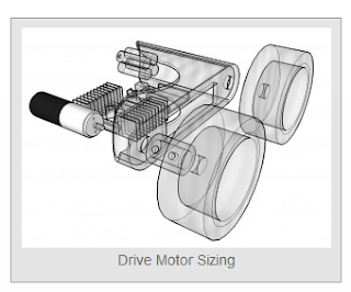
That narrowed the space a little. But, being new to the world of motors, I was still a little lost. Motors come with a set of specification to inform users of what they are capable of, but I wasn't very famliar with what they mean or what I needed for my drivetrains. After slogging through sever rather dense explanation of motor specs, I had a little better idea of what they were, but still didn't have much of a feeling for what my robot would require. The main specs for motors are torque and rotation speed, and in general, increasing either of those increases both the cost and how much the robot is capable of. So I needed to figure out the minimum torque and speed required to make my robot work. Luckily, I found an AMAZING tool for exactly that purpose at RobotShop.com.

This calculator is a godsend.

I assumed that the RobotShop calculator was based on the premise that the robot would be running on a hard surface, like concrete, and I intuitively felt that running on sand would be more difficult (and therefore require more torque). So when putting in the parameters, I wanted to err on the side of overestimating how much torque my motors would need. I played around with the calculator and found that to increase the amount of torque required, you can either increase the mass of the robot, decrease the number of drive motors, increase the radius of the drive wheel, increase the maximum incline the robot will need to climb, and/or increase how quickly the robot will need to accelerate. Here are the parameters I put into the calculator:
  • Mass: 15 lbs. The robot will have drive motors, limbs, Arduino and circuit, obstacle sensor, a plastic box to hold and protect the electronics, a search coil, and maybe some PVC structure. Since it'll be small and mostly plastic, I think 15 lbs is a high estimate.
  • Number of motors: 4. The wheeled design calls for 4 motors, the C-limb design for 6. Four seemed like an appropriate underestimate, since I can always give the wheeled design six wheels if four doesn't cut it.
  • Wheel radius: 3". The wheels I have on hand (from the toy trucks) have radii 1.5" and 2", so 3" is a comfortable overestimate.
  • Robot Velocity: 1 ft/s seemed like a fairly quick speed for a metal detector. Velocity has no impact on torque needed, but does affect the rotational velocity needed. 
  • Maximum incline: 10 degrees. The robot will be moving on a beach, so I don't anticipate that it will need to climb much incline.
  • Voltage: 6V. Doesn't affect torque or rotational velocity, so I just guessed.
  • Desired acceleration: 0.2 ft/s². If my robot's maximum speed will be 1 ft/s, then accelerating at 0.2 ft/s² would bring it up to full speed within 5 seconds. I can live with that.
  • Desired operating time: 1 hs. I would like the robot to run as long as possible, but I can live with changing the battery every hour or so.
  • Total efficiency: 65%. I left it at the default.
 With these parameters, the calculator advised me that I would need motors with torque of at least 3.58 kg-cm and 4 rad/s (with smaller wheels, I would need more rad/s).

With those specs in mind, my next step was to look for specific motors that meet them. I looked on Robotshop, Amazon, and eBay; unfortunately, most servos offered between 1 and 2 kg-cm of torque. I was most impressed by the TowerPro SG5010 servos on Amazon, which were $5.17 each. The Amazon description says they take voltage between 3.5 and 8.4 volts, and gave the torque specs as stalling at 8 kg-cm when powered at 4.8V and 11 kg-cm for 6V. That seemed almost too good to be true, since other sellers were offering a lot less torque for a lot more money. I checked the specs for the same motors on another supplier, iMall, who says the operating voltage is 4.8V to 6V and the torque is 5.2 kg-cm to 6.8 kg-cm. Not exactly what was advertised by the Amazon supplier, but luckily still sufficient for this project. I ended up ordering six of them, for a total of $31.02.

The TowerPro SG5010

Next, I needed a way to control the motors. One of my friends, who's built an RC car before, warned me that Arduinos can't directly power servos. He recommended using H-bridges, little chips that act as a go-between for the Arduino and the servos. However, I was concerned that between the six servos and the other sensors and things I'm using, the Arduino might not have enough pins available to control all the H-bridges. I started shopping around for motor shields, which would effectively create more pins for the servos to interface with, replacing H-bridges as the middleman. I decided to go with the 16-channel motor shield from Adafruit for $17.50. Since it can control up to 16 motors from one Arduino, it's more than sufficient for this robot, and it should be well-suited for any future project I can come up with.

Runs 16 servos off of two Arduino pins!

The last piece of the puzzle was finding a battery to power the motors. This Adafruit article recommends using separate power supplies for the Arduino and the motors, so I decided to do that. I won't go into too much detail about how I chose a battery, but after reading a lot of comparisons of different kinds of batteries, I decided to go with LiPo batteries for the motors and 9V Duracells for the Arduino. The motors need a voltage of either between 3.5 and 8.4V, or 4.8 and 6V (depending on whether you believe the Amazon seller or the iMall seller), so I decided a 6V battery would do nicely. LiPo batteries don't come in 6V- the closest you can get is 7.4V, so I decided to go with that, and also ordered some adjustable voltage regulators (LM317T) on Amazon ($6.19 for 10). This will allow me to set up a circuit to lower the voltage across the motors to 6V. The RobotShop motor sizing tool also tells you how much battery capacity ("battery pack") you need to run the robot you describe. Battery capacity is measured on battery descriptions in units of mAh, although the RobotShop tool gives it to you in units of Ah. For the inputs I described above, I need 938 mAh in order to run the robot for 1 hour on a single battery. More mAh means the robot can run longer at those specs, and gives me some wiggle room on my estimates. In the end, I ordered three 7.4V LiPo batteries of varying capacities, and a Tenergy charger from Amazon for $32.88.

If you've never done this kind of project before, hopefully this post has given you some insight into how to begin. In the next few days, I'll be post an update on my progress with metal-detecting.

Wednesday, June 17, 2015

Drivetrain Designs

In this post, I will give an overview of the drivetrain designs I've come up with and reveal which ones I've decided to prototype. After browsing Pinterest and Instructables, I found six ideas for drivetrains to travel on sand.
1. Four Wheels. This is the most common type of drivetrain for RC vehicles, and there's no shortage of tutorials for how to make a small four-wheeled robot. This one uses four motors, while this one uses two. A four motor design is simple- each motor drives one wheel. The two-motor tutorial uses an RC truck as the base, and didn't really modify the drivetrain, so the tutorial doesn't provide much insight into how it works. However, in FRC we drove multiple wheels from one motor by chaining them together, and I assume the RC-truck-based drivetrain uses a similar principle:

This drivetrain has six wheels, but it uses the same principle. Image Credit: http://www.robotshop.com

However, since this robot will be driving on sand, I want to minimize the number of exposed parts that sand can get into and damage, so it would probably be better to use four motors. I would also want to use wide wheels, with large surface areas, to help keep them from sinking into the sand.

2. Two Wheels. A lot of Instructables (Obstacle Avoiding Arduino Robot, First Robot) for basic robots use two driven wheels, usually with some kind of passive roller in the back for balance. This would be simpler and cheaper to build, but I'm not sure it would have any advantage over a four-wheeled vehicle in its ability to move in sand.

Image Credit: http://www.instructables.com
 
3. Six C-Limbs. This one's really cool. I referenced it briefly in my last post.

Image Credit: http://blogs.scientificamerican.com

The robot, called Sandbot, was built by a team of researchers from Georgia Institute of Technology, Northwestern University, and the University of Pennsylvania. It has six comma-shaped limbs, called C-limbs. I wanted to see how the limbs move, so I looked it up on YouTube and found this video from NPR.


The limbs move three at a time- the outer two wheels on one side are synchronized with the middle wheel on the other side. The video also revealed that the timing of the c-limbs' rotation is critical. Each rotation has a slow phase (the part where the limbs are in the sand) and a fast phase (the part where the limbs are out of the sand). The timing of switching from fast phase to slow phase is the key to Sandbot's ability to move so quickly through sand.

4. Tank. Tanks are designed to be all-terrain vehicles, so I thought a tank-style drivetrain might do well on sand. This Instructable shows how to make cheap, customizable tank tread out of PVC and bike chain.

Image Credit: http://s356.photobucket.com

5. Simple Walker. The first four ideas were essentially variations of wheeled vehicles. The next two are variations of walking robots. This Instructable shows how to make a very simple walker with two motors, which drags its feet as it moves. Spatula feet would immediately sink into the sand, so it would need to have a different type of foot. I think something with a large surface area would be best (the same principle as snowshoes).


6. One-Motor Walker. This one's intriguing. It uses one motor to run its four legs, and it moves like a lizard. Lizards are evolved for deserts, so I thought maybe its gait would do well on sand.


Like the simple walker, this one would need some kind of wide feet to keep it from sinking in sand.

Next, I needed to choose two or three ideas to prototype. The two wheel design is interesting, but I was concerned that its balance issues, even resting on a rear roller, would make it difficult to install the metal detector's search coil in a way that would keep it parallel to the ground. I'm also not convinced that it would have any advantage over the four-wheel design, so I decided to put the two-wheel design aside for now. I love the idea of the one-motor walker, and I want to make one eventually just because it's cool. However, the gears have to mesh in the middle of the bot, which is where I want to put the search coil. So that's off the table for this project as well.

I knew I definitely want to try the six C-limb design, and while I'm prototyping that, it would be easy to prototype the basic four-wheeler as well- it would be the same motors and chassis, and all I would have to change is the attachments on the motors. I decided to prototype some version of the simple walker too, because it's so different from the wheels and C-limbs. I'm intrigued by the tank idea, but making the tread seems very time-consuming. I also know from FRC that dealing with chains can be a real pain, and having chains and sprockets would create another mechanism that would be vulnerable to sand. But if the four-wheel prototype doesn't go well, I'm going to try attaching PVC pieces to the wheels in a sort of chain-free version of the DIY tank tread. Since the main function of the chains is to help the tank go over obstacles, and I don't anticipate many obstacles on the beach, I think a chainless-tank-tread idea could potentially work well.

Having decided which designs to prototype, my next step was to figure out what parts I needed to order. Most online tutorials skip over this step, since their purpose is to teach you how to build what they built, so they just tell you what parts you need. However, if you are trying to get into designing projects like this as a hobby, learning the process is valuable, so I'll go over it in my next post.

Saturday, June 13, 2015

Choosing a Metal Detector Circuit

Since my last post, I've learned more about different types of metal detectors and how they work. I decided on a circuit to build, and ordered the necessary parts. I also got the webcam from the swap met to work, and started thinking about drivetrain designs.

After reviewing several metal detector schematics, I've decided to make an Arduino-based metal detector that uses the BFO principle. I started by reading up on how metal detectors work on How Stuff Works. There are three types of metal detectors:

1. Very Low Frequency (VLF). The part of the VLF metal detector that skims along the ground has two concentric coils. The outer coil is called the transmitter coil. The metal detector circuit runs electric current through it, which generates a magnetic field perpendicular to the ground. The circuit reverses the direction of the current, typically hundreds of times per second, which changes the polarity of the magnetic field. The number of times the current changes direction per second is called the frequency of oscillation, or sometimes the frequency of the coil. As the magnetic field pulses into the ground, when it hits a conductive object, the object starts generating its own weak magnetic field. The inner coil, called the receiver coil, is shielded from the magnetic field of the transmitter coil, but not from magnetic fields coming from the ground. When it encounters a magnetic field coming from the ground, an electric current runs through the transmitter coil, with the same frequency as the object's magnetic field, which allows the metal detector to detect approximately how deeply the object is buried and what kind of metal it is. Most consumer metal detectors are VLF.

VLF Illustration. Image Credit: http://electronics.howstuffworks.com

2. Pulse Induction (PI). The metal detector sends short bursts of current through the search coil, which sends brief magnetic fields into the ground. If the coil is over a metal object, the object generates an opposite magnetic field, and the search coil's pulse takes longer to fade. It's a bit like echolocation, but with magnetic pulses instead of sound. PI detectors can't really discriminate between different types of metal. However, they're good for when there's conductive material in the environment, like for salt-water exploration.

3. Beat-Frequency Oscillation (BFO). The circuit runs current through the search coil, switching current direction many times per second (much like the transmitter coil of the VLF). When metal is moved near the search coil, the coil's frequency changes. A second coil, the reference coil, is turned to have the same frequency of the coil changes. A second coil, the reference coil, is tuned to have the same frequency that the search coil has when not near metal. The two frequencies are fed into the circuit, which translates the difference between the frequencies into a user-friendly signal, like an audible tone or visible meter.

Armed with that knowledge, I started looking up metal detector schematics. I found four pretty simple ones:
I found this site especially cool- they give a really thorough description of several circuits, starting with a very basic metal detector and working up to more complex ones.
 Since I want my robot to eventually run autonomously, it needs to have a "brain" onboard. Since I've worked with Arduino before (for a full account of that adventure, you can read the blog posts from the research lab I worked at last summer), I decided to use an Arduino Duemilanove. To quote my post from last summer, "Arduino is a brand of microcontroller board designed to help you quickly build circuits and write programs that interact with the physical world. You can think of an Arduino as a tiny, and limited, computer. You can write programs on your laptop or desktop, then upload them to the Arduino board through a USB cable." Since I'll be using an Arduino anyway, I thought it would be simplest to have the Arduino read the metal detector too, so I went hunting for an Arduino-based metal detector schematic. I found a really extensive discussion about metal detectors on the Arduino forum, but in the end I decided to follow a design from Dzl's Evil Genius Lair.

Image Credit: Dzl's Evil Genius Lair

It's similar to a BFO metal detector. However, instead of comparing the search coil frequency to the frequency of a reference coil, the Arduino compares the search coil frequency to a stored value. To calibrate the metal detector, you power on the circuit with no metal around, and then press the null switch to record that search coil frequency. The Arduino stores that frequency, and reports that metal has been detected when the search coil frequency differs from that stored value. I'm not sure what a null switch is, but from Dzl's description of what it needs to do, I think I can use one of the pushbutton switches that came in my Arduino starter kit.

Image Credit: http://www.smcelectronics.com/SW52.JPG

The starter kit also included a little Piezo buzzer, which I probably won't use in my final design, but it could be useful for testing the circuit. Or I might use an LED and have it get brighter when metal approaches. I ordered variety packs of resistors and capacitors from Amazon, which will be useful for future projects as well. I also ordered a transistor, on eBay- commenters on Dzl's blog had trouble getting it to work with the 2n2222 transistor, so he now recommends the BC547 transistor. The capacitors arrived today, and I have the necessary resistors in my Arduino started kit, so as soon as the transistor gets here I can start building the circuit. I also have to decide which appliance motor I'm going to sacrifice for its enameled copper.


This week, I got my USB webcam to work! It would be really cool to be able to watch live video from the robot on a computer or tablet (probably tablet, since I could put it in a gallon-sized Ziploc to keep sand out of it). Someone at the swap meet a couple weeks ago was selling a Logitech webcam for a dollar, so I took a chance on it. It's a Logitech Quickcam, model number V-UBG35.

Image Credit: www.laptopsolutions.ca

I plugged it into my laptop, and my family's desktop, and all it would do was try to install drivers and then give me an error message. It turns out that the V-UBG35 was designed for Windows XP and Vista, and isn't compatible with Windows 8. Luckily, I found software (LWS 1.1x64 with Vid) on the Logitech support site to make it compatible with Windows 8, and ran the Windows Program Compatibility Troubleshooter (as described here). The webcam works now; the video quality is grainy, but might be good enough for this. All I really need is to be able to see when it's heading towards water or an obstacle, so I can power it off or make it turn around (if it fails to turn on its own).

In my next post, I'll talk about my progress on drivetrain designs.

Monday, June 8, 2015

Learning about Metal Detectors and Taking Things Apart

Two weeks ago, I picked up some junk at the swap meet, in the hopes that I would be able to salvage some parts. For $16.50, I got two electric mixers, a blender, a small fan, an Arduino-compatible USB cable, a Logitech webcam, and a toy truck. This week I took some of those apart, researched metal detectors, and took the SuperNURDs to a competition at the fair.

I originally thought I might be able to re-purpose the motors from the appliances for the robot, but it turns out that anything that plugs into the wall runs off of mains supply, which in the United States is 120V. The highest voltage battery I would possibly use for this robot is probably an 18V drill battery, so I won't be able to use a motor that needs much more than that. It is possible to increase voltage between the battery and the motor using an electrical component called a transformer, but transformers that can increase voltage from 18V to 120V don't seem to be commercially available and at this point I'm thinking it might not be worthwhile to try to hunt one down and figure out how to use it.

My next thought was that some of the appliances might have motors that actually run off lower voltages, and have circuits that step down the voltage for them. So I opened up one of the mixers to check it out.


The motor inside the mixer was labeled as being rated for 120V, so no luck there.

I also took apart the blender. There was a weird triangular screw holding the bottom on, and I couldn't get it off with a flathead screwdriver, so I drilled out the screw. Companies usually use unusual screws like that when they want to keep people from opening a device- if you can't open a device, you can't repair it and you have to either buy a new one or pay to have it repaired by a professional.


The blender motor doesn't seem to be marked with the voltage it takes, and there's a small circuit board inside that could potentially be lowing the voltage. It seems unlikely that it would lower the voltage by much, when they could instead use a motor that is suited to mains voltage, but I'll take a closer look at the circuit over the next week and hopefully be able to talk about that in my next update.

Top: Disassembled blender; Bottom Left: Blender circuit; Bottom Right: Blender motor

When I bought the toy truck, I thought it was just a basic toy with no electrical components, and I thought I might be able to use the wheels or the jointed arm for something. When I got home and started looking at it more closely, I saw that it has a battery compartment. I put in three batteries and tried flipping the on/reset/off switch and moving the knobs, but nothing happened. So I opened it up, in the hopes that I might be able to figure out what was broken, or at least salvage some electrical parts.


The truck has a speaker, a small motor that turns the arm in the truck bed, an adorable little gearbox, and a bunch of LED lights. It also has some kind of little switches that look like they're supposed to be triggered by the doors opening and closing.

The gearbox (which was full of mud), the speaker, and the switch that's triggered by the truck door.

One of the leads on the motor was broken. I'm not sure if that's what was wrong with the truck (it seems like some of the other functions should still work, even if the motor was disconnected), or if I accidentally broke it while taking it apart. I'm going to solder the connection back together, and see if it works any better then. If the truck still doesn't do anything, I'm going to try putting the batteries back in, switching it on, and measuring voltage and current through various parts of the circuit and see if I can diagnose anything.

I did some internet research on metal detectors this week, and found a ton of different DIY metal-detecting circuits from various websites. I learned that the search coil of a meal-detector (contained in the disc at the end of the handle) is the part that controls what you can detect. The search coil is a coil of wire, usually enameled copper. The larger the circumference of the coil, the deeper it will be able to search. However, as the coil gets larger, it becomes less sensitive and loses the ability to find small objects like coins. I'll experiment with different size coils once I figure out what circuit to build. I think it could be cool to have two search coils on my robot (one to look for small objects near the surface, and one to look for larger objects deeper down). I suspect that the coils might interfere with each other, but since I'll be making a couple different sizes of coils anyway, it's worth a try. I also learned that enameled copper is what they use in motors, so even if I can't use any of the appliance motors as motors, I can at least cannibalize them for wire.

Image Credit: http://phandroid.com/2009/05/03/android-metal-detector/

 I went to the beach on Sunday, and brought my dad's old metal detector. It has a pretty small range- it was able to detect a ring of keys from two or three inches above. I walked around the beach for 20 minutes or so, and didn't find anything. I learned that you have to keep the search coil close to the ground, almost skimming the sand, since it has such a short range, and that people usually sweep it back and forth as they walk, so that they search more area per distance traveled, which are both important things to keep in mind as I design the robot. There were a lot of people at the beach, and I started thinking that if the robot is going to run autonomously (or semi-autonomously), it will need to be able to avoid crashing into people and their stuff. I saw a tutorial a couple weeks ago on how to build an obstacle-avoiding robot using Arduino and an ultrasonic sensor, so I will probably end up adding obstacle-detecting capability to my robot.


While I was walking around with the metal detector, I also started thinking about whether it would be better to build a wheeled robot or a walking robot. I've only ever worked with wheeled robots, so that's definitely more in my comfort zone. However, I know wheels tend to get stuck in sand (this site gives a particularly thorough explanation of how to drive in sand to avoid getting stuck, and the gear you should bring to help extract your vehicle when it does). I think this risk can be limited by keeping the robot light and using wheels with a large surface area, but it might by easier and/or more effective to build a four- or six-legged walking robot. Since it would pick up its feet, it would be less likely to get itself stuck. On a related note, these researchers at Georgia Institute of Technology, Northwestern University, and the University of Pennsylvania built a walking robot that can travel at almost one foot per second. They said that when they programmed the robot's legs to move faster, it got stuck in the sand, so they had to find the maximum speed that allowed it to actually move.

In other news, my team competed in an off-season event at the San Diego County Fair on Saturday! We placed last (out of a total of eight teams), but we had a blast. Out underclassmen were driving and this was their first competition as drivers. By the end they were doing pretty well, but there was definitely a learning curve. We also got to show off our robot and talk to passersby about FIRST- one man I talked to was at the fair with his daughter, and they were really excited. They had tons of questions about the competition- in the father's words, "I'm such a geek aobut this stuff- building a robot like these, I wouldn't even know how to begin, but it's just so cool." He said they would stay and watch a match, and then they ended up staying until the end of the competition. Part of FIRST's mission is "To transform our culture by creating a world where science and technology are celebrated," so I thought it was really cool to have someone who's not an engineer stop by with his daughter and get so excited about the competition.

Left: Grace drives, while Matt coaches and Otto feeds the robot totes. Right: Our bot, 3255, lines up with the feeder station.

Saturday, May 30, 2015

Embarking on a New Project

My courses at Mudd have been more on the abstract side lately, so I was in the mood to do a more hands-on project. After working with the SuperNURDs this semester, I was inspired to build a robot of my own this summer. After much thought, I decided to build a metal-detecting robot. Over the course of the season, we've spent a lot of time analyzing FRC games, and I've been thinking about how cool it would be to build a robot for terrain other than the standard carpet-with-obstacles that FIRST usually goes for. Like sand, or ice. Then I saw a tutorial online for how to make a metal detector. I put the two ideas together, and decided to build a treasure-hunting beach robot.

The most basic version is a remote-controlled robot with built-in metal detector, that can be driven on sand (i.e., the beach), and indicates to the user when it has found metal, maybe by beeping. However, there are a lot of other features I'd like to build in if time allows. I would love to make it able to drive autonomously, to roam around the beach looking for metal the way that Roombas drive around rooms. I would keep some control over it though- at the very least, I want to be able to tell it to stop, or turn around, if it starts heading toward the water or a group of people. It would be really cool if it could sense when it's getting too close to the water and turn itself around- I've seen some projects where people used moisture sensors to monitor when their plants need to be watered, so it should be possible to give the robot the ability to know when it's near the waves. I plan to make it as waterproof as possible, but I would still like to have a remote-control failsafe. I also want to set up a live video feed from the robot to my computer, so that I can see where it's going.

If I get those things working before summer ends, I'm going to build in the capability to collect the metal it finds. There are two pieces to it: digging in the sand, and picking up and storing the metal. The digging part shouldn't be too difficult to work out- I think the biggest challenge will be teaching it to recognize and pick up the pieces of metal it digs up.

So those are the features I've been thinking about for the robot. In my next post, I'll explain the parts and resources I've collected so far.